Journey & design process
This is the documentation of how Box Bot evolved over time, from a concept to a fully autonomous box moving system.
Sprint 1/Phase 2: Ideation and Prototyping
INITIAL STAGES & DESIGN PROCESS
Group formation, timeline managements, and design process.
Group Formation & Roles
Our team came together because of our interest in creating a strong project to put on our personal portfolio. When discussing project teaming and agreement, we came up with these following rules:
- Commitment: Spend 5-7 hours outside of class on a typical week, 30-40 hours in the last week.
- Expectations: Call people out if someone is slacking off, and if it gets worse, involve the teaching team.
- Project Manager: We decided a Project manager system, where Heesung will manage timelines and making sure work gets done.
Timeline Management
To ensure that we stayed on track, we used a Gantt chart to visualize the project timeline and assign clear, descriptive tasks to each team member. This improved accountability and helped us better understand how limited our time was for completing the project.
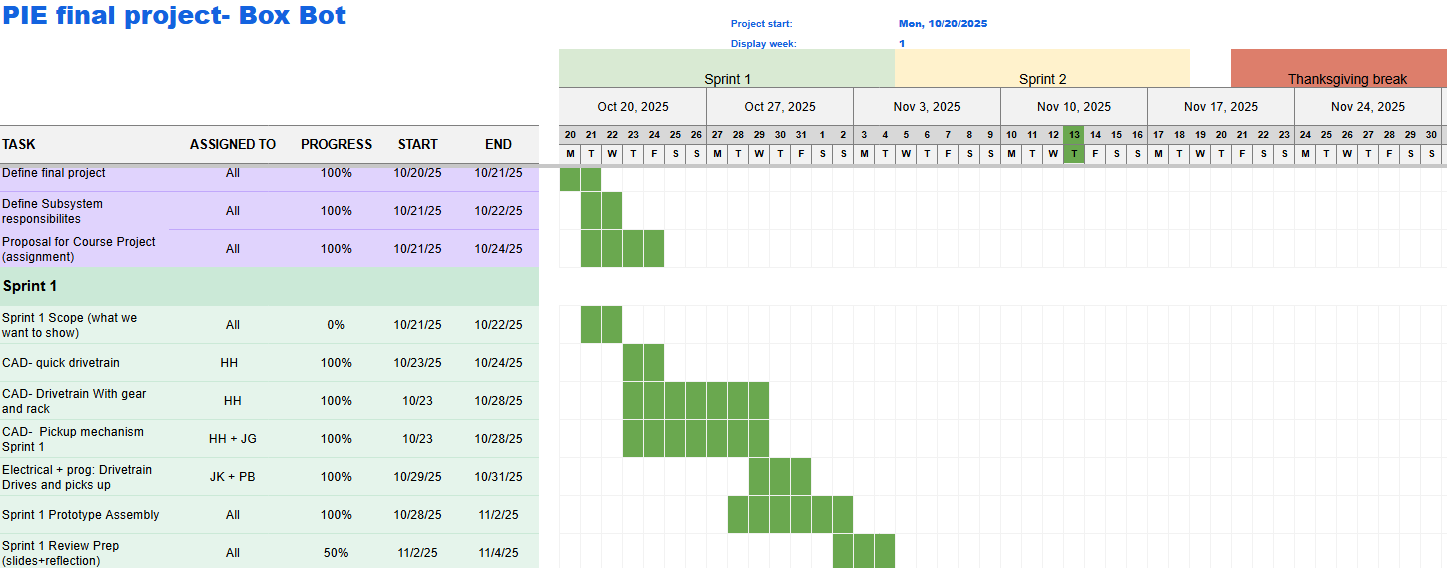
Figure 1: Sprint 1 Schedule- Gantt Chart
Honing a Singular Idea
We had many ideas, such as a Red Light Green Light Robot, CNC Tube Notcher, wall climbing robot, and more. Using a Pugh Matrix, we ended up with BoxBot because it was something that everyone was committed to do, it was complex, and it was scalable to be more difficult/easier. At this current stage, we didn't know exactly how we wanted to manipulate the box.
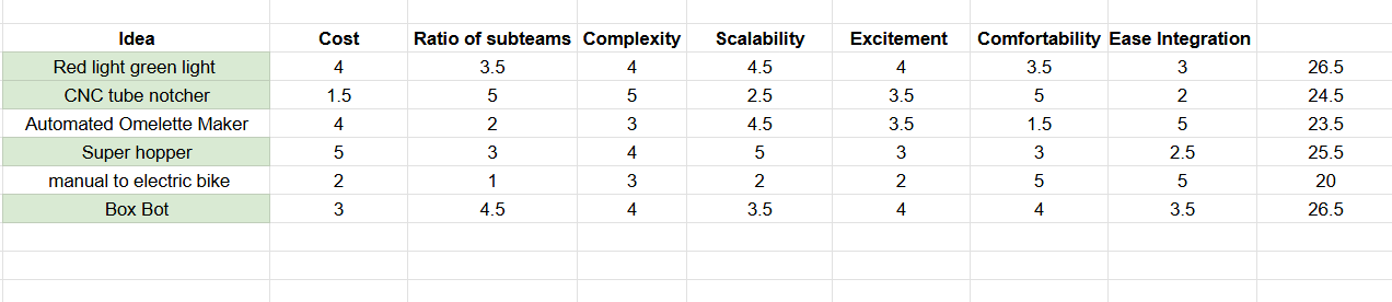
Figure 2: Pugh Matrix Chart
Figuring out the weeds
After settling on what we wanted the project to do, we spent several days figuring out what mechanism we wanted on the BoxBot. After several hours, we ended up with a U shaped robot, where the sides will be moved by a rack and pinion system while the box will be lifted up through a mechanism.
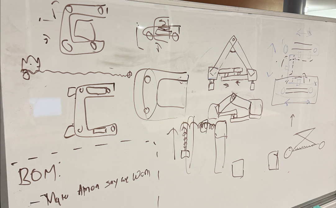
Figure 3: Ideation board
Design Process
Although we will dive deeper into the design in itself throughout this website, there were several design decisions we had to come up with.
- Chassis Geometry: Originally, we wanted to lift the box in front of the robot. However, we came to the conclusion that it was too similar to a forklift. Because this was something that we didn't want to do, and that we wanted to make something more unique, we decided to lift the box by sandwiching it. This made the design decision as a U-shaped Chassis.
- Box manipulation: Since we figured out we wanted a U-shaped Chassis, we then had to figure out how exactly we wanted the robot to be in contact with it. We knew that the 2 sides of the chassis had to squeeze, but we were deciding between a scissor lift that open and closes left, a rack and pinion system, and a belt system. We decided to go with a rack and pinion system because this was something we could rapidly test and 3D print. We had to wait for the belt system, so we came to the conclusion that rapid iteration will be more worthwhile.
- Box Lifting: We had to figure out how we wanted to lift a box. We ended up with a scissor lift mechanism on both sides. Since we had supports of both sides, we figured we can have a lift plate that gets under the cardboard box.
MECHANICAL
Designing the U-shaped chassis with 3D prints
ELECTRICAL
Wiring and getting the robot to drive
SOFTWARE
Getting basic functionality down
Chassis Design with Rack and Pinion
Our goal was to validate the U-shaped drivetrain. Having designed based on the mini-project 3, we separated the two sections and added a rack and pinion on the other side. This rapid prototyping was able to help us test the squeeze functionality with the rack and pinion. The learnings that the mechanical team had was to switch to Omni Wheel, and have a middle section to keep the electrical in place.

Initial U-shaped chassis CAD with 3D printed components
Driving the prototype
Our initial electrical system was an evolution of MP3. Our goal was to re-use as many components as possible that we already were familiar with and that we had easy access to. We used an Arduino for logic and a motor shield for motor control.We supply the power to the motor via a wall outlet, making this prototype tethered. One takeaway from this prototype was the challenge of wire management on a robot that changes size, a challenge that we experienced throughout the design process.
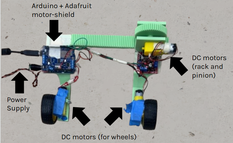
Electrical Diagram of the prototype robot
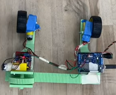
First prototype electrical system
Drive functionality
We focused on building basic driving functionality code. We got forward, reverse, close, and release to all work. This was all controlled through serial connection to a laptop. Testing with a wired USB cable for serial connection proved cumbersome, prompting us to move to an alternative onboard microcontroller/computer for the next phase.
Video of our Sprint 1 Product driving
Programmed with Arduino IDE
Phase 3: Update on Integrating, Reflecting, and Iterating
MECHANICAL
Drivebase and scissor lift updates
ELECTRICAL
Battery and Raspberry Pi integration
SOFTWARE
Defining software architecture
V1 Drivebase updates
Throughout phase 3, we went through 2 different iterations of the design. Version 1 had a rack and pinion system driven by a stepper motor, where we left room for electrical in the back. We also added omni wheels for easier side to side movement with multi-directional caster wheels to support the weight of the robot and the box.
Some of the changes we needed to make was that the caster wheel was misaligned with the omni wheels, the necessity of linear rails for stability and precision, Camera Mounts for Vision, and a better support system for the rack so it doesn't wobble.
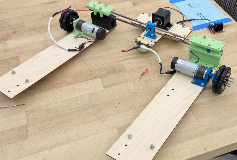
V1 of the Drive Base made of laser cut and 3D printed parts
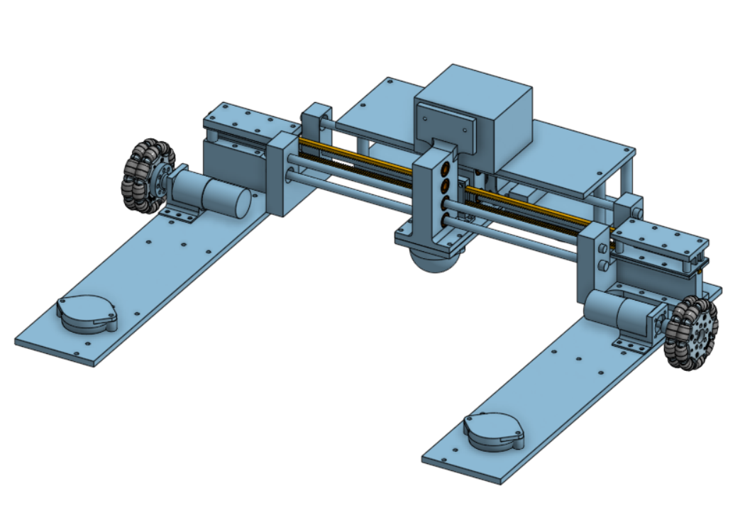
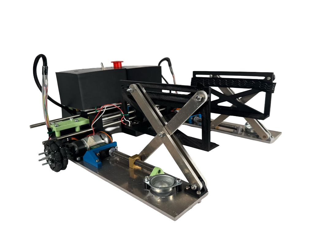
V2 Drivebase updates
For version 2, we added linear rails for stability, and made sure that the omni wheels and the caster wheels were designed to keep the robot parallel and as low to the ground as possible. We also added the 3 caster wheels on the center plate for more support. Something that we also worked on was keeping the rack stable, so we created rack guides that helped stabilize the drive base. The camera mount was designed as well.
Some of the changes we need to make was a adjustable camera mount, have extra caster wheels on the drivebases, and make space for electrical mounting. We also needed longer linear rails, and have the linear rails sandwich the rack and pinion system.
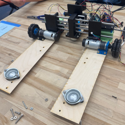
V2 of the Drive Base made of laser cut and 3D printed parts
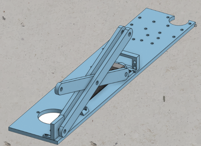
Scissor lift updates
For the scissor lift design, we used a lead screw, where we were projected 1 inch of lift. We used 3D prints and wooden prototypes to create this.
Some of the changes that we needed to do was optimize the brackets, and we had to design for a full lead screw instead of a bolts.
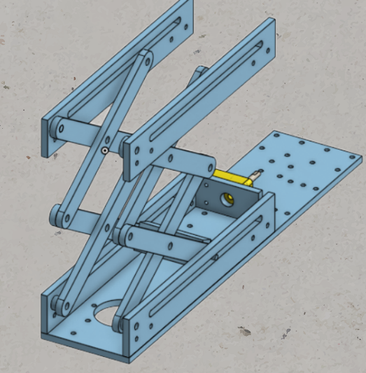
Scissor lift CAD
High-Power Integration & Safety
In Phase 3, we switched to a battery powered system. We finalized the power distribution with our 24V battery and tested motor controllers for drive and squeeze motors. To ensure system longevity and safety, we integrated a 6-circuit LED blade fuse block, protecting individual subsystems from overcurrent. We also switched to our final compute platform: the Raspberry Pi 4b.
- Fuse Block: Safety protection for the Raspberry Pi 4b and sensors.
- Sabertooth 2x12: Dual channel DC motor control.
- L298N Dual H-Bridge: Stepper motor control.
- Raspberry 4b: WiFi-enabled single board computer
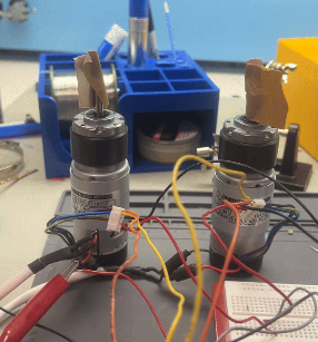
Testing DC motors
Software Architecture
Our software underwent a complete overhaul for this phase, evolving from basic serial control to a robust ROS2 Python software stack onboard the Raspberry Pi. Within the ROS2 ecosystem, we defined scaffolding for all software we would need to create. We created Nodes for teleoperation control, autonomous control, and drive logic. In this phase we successfully tested the teleoperation and drive control nodes, and laid the groundwork for future work with computer vision for autonomous driving. By the end of this sprint, we were able to wirelessly drive the robot and squeeze objects.
- Teleoperation Node: Accepts keyboard input to drive robot and squeeze/open rack and pinion system
- Drive Node: Listens for commands from either teleoperation or autonomous Nodes. Sends necessary GPIO signals to drive and squeeze motor controllers.
- Autonomous Node: Created basic setup to communicate with RealSense camera.
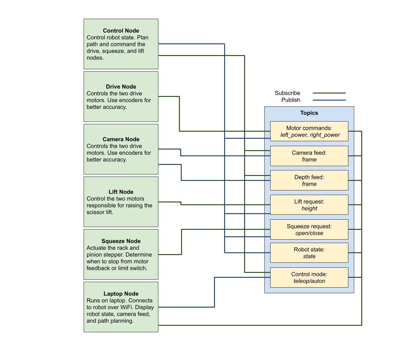
Old ROS architecture, later simplified
Phase 4: Update on Refining Resourcefully
MECHANICAL
Final drivebase assembly and scissor lift progress
ELECTRICAL
Finalized wire harness
SOFTWARE
Drive control de-bugging and autonomous progress
Final Drivebase CAD
To start this phase, we updated the drivebase CAD where the linear rails sandwiched the rack and pinion system, the back caster wheels were attached, and the center plate became 5 inches longer.
Some of the changes we needed were the electrical covering as well as the electrical mounting plates.
CAD of the final Box Bot Drivebase
Drivebase fabrication
Using 1/4" Aluminum 6061, we water jetted the drive-base plates, as well as the scissor lift arms.
CAD of the final Box Bot Drivebase
Scissor Lift Progress
The Scissor Lift has got some updates. They include the design adapting for the final lead screw and around space constraints, designing around the lead nuts, and the the 3D printed mounts.
Some things that are still in progress is the full assembly as well as we have to print the scoops.
CAD of the updated Scissor Lift
Wiring Finalization & Protection
We spent a significant amount of time creating a finalized cable routing solution to prevent interference with the moving rack and pinion. We made custom length wire harnesses with quick-disconnect DuPont-style connectors for all components. We also used a solderable breadboard to create a permanent junction box for all components. All logic level connections followed standardized wire color rules. We also ensured our digital wiring diagram aligned with the physical system exactly. At this point, we also properly implemented our emergency stop button and fuse block. These measures protect the user from an out of control robot and the components from over-current.
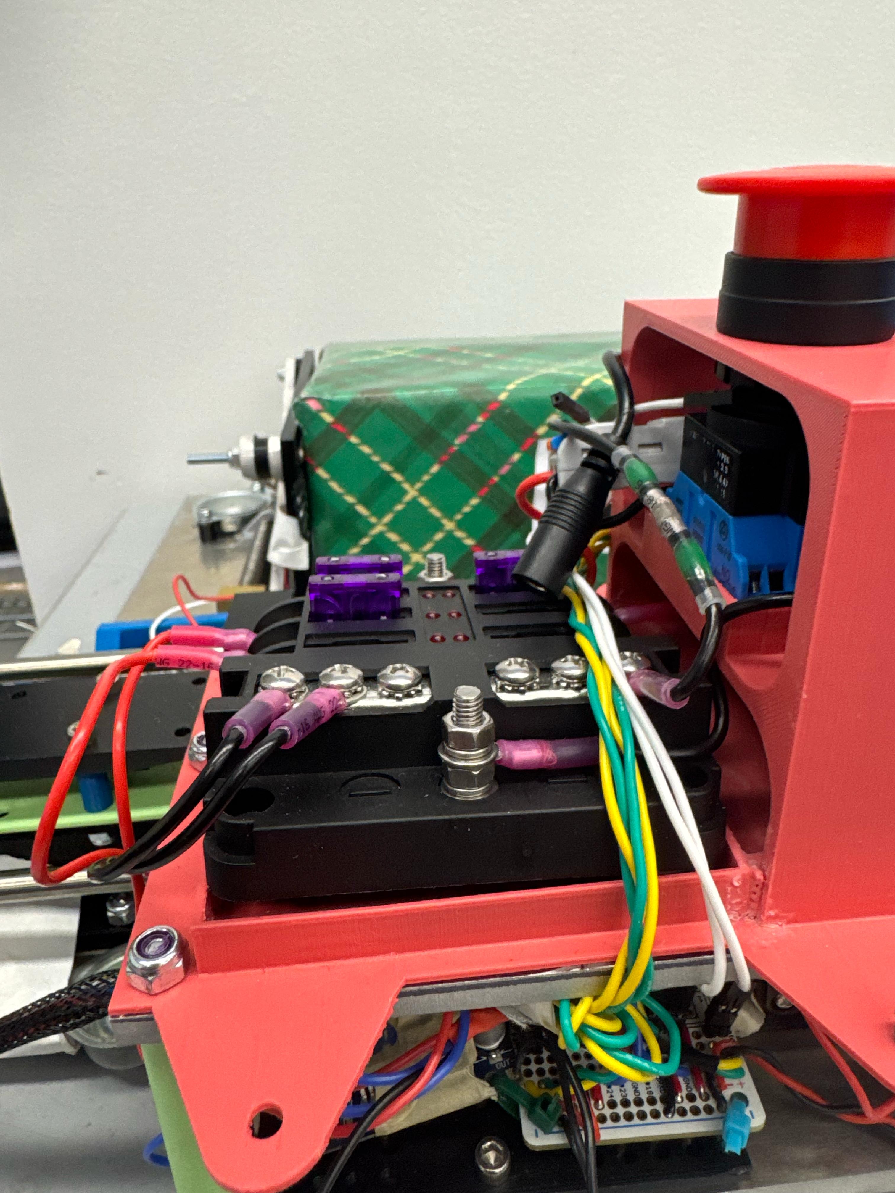
Fuse block fitted with current-limiting fuses
System Tuning & Autonomous Groundwork
We moved into the refinement stage for our drive software, ironing out bugs with drive code, getting to the stage where our robot reliably operated under teleoperation mode. With this accomplished, we were able to turn our attention to autonomous, which we worked on in parallel with the drive code updates outside of the ROS environment. We were able to detect April Tags with the camera, and generate simple drive commands to follow the tags. Unfortunately, we encountered a major roadblock when attempting to integrate this code into our ROS environment, and lost significant amount of time to resolving dependency issues with the RealSense Python library. As a result, we were unable to test autonomous before the end of the sprint, as originally planned.
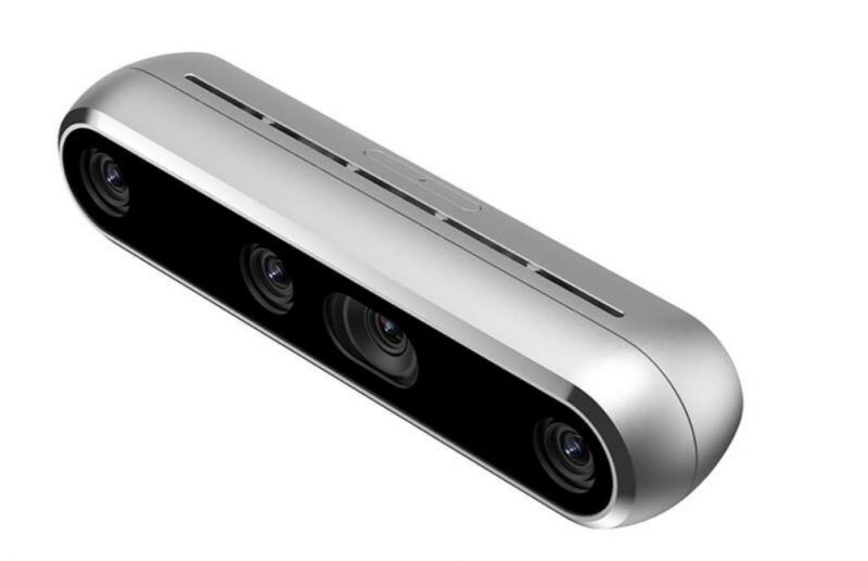
RealSense D455 depth camera
Pre-Demo Day: Further Refinement
MECHANICAL
Final touches on drivebase and scissor lift
ELECTRICAL
Refinement and mechanical integration
SOFTWARE
Autonomous development
Electrical Covering For the Center Plate
In order to protect and make our final product clean, we decided to make electrical covering and mounts for the plate. Starting with the electrical mounts, we measured all of the different electrical components to press fit into the 3D print. We also created electrical covers that had holes opening for only the E-Stop.
CAD the electrical covering
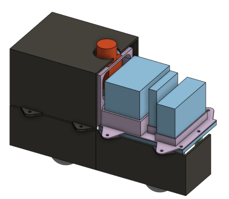
Scissor Lift Design and Assembly
We fully implemented our final scissor lift design and solved several issues that arose during integration. Mainly, we had to figure out spacing issues to fit the servo motors with the DC motors. We went through several iterations of mounts before arriving at a design that would comply with the DC motors without sacrificing over all lift height. One we had everything packaged properly, we worked to improve the overall stability of the scissor lift. The final piece of implementation was fixing the lift plate to the lift arms.
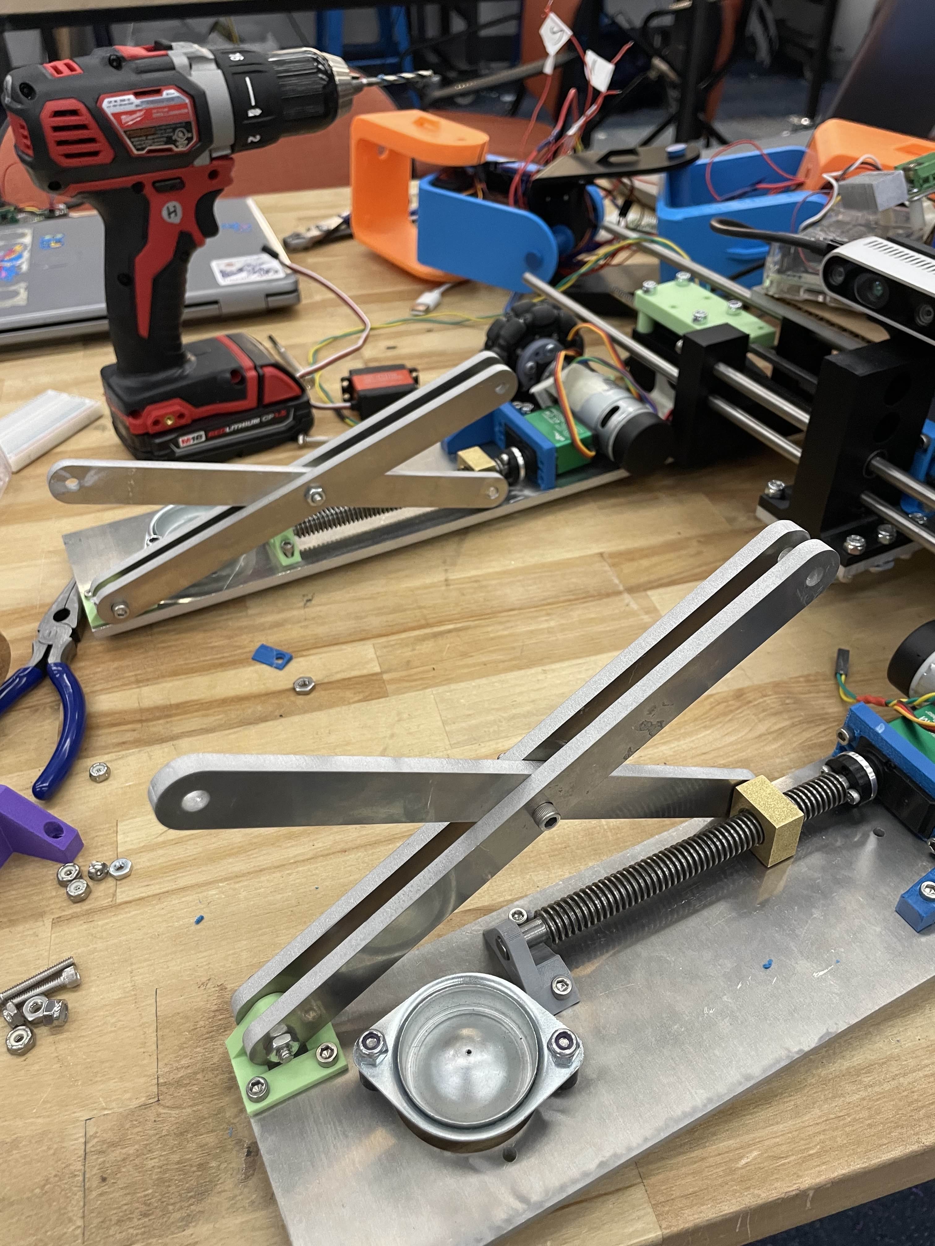
Assembly of the Scissor lift
Final Component Integration
In the last sprint, we had finalized our core wiring harness, allowing us to move into a refinement stage. We completed the final connections to the servo motors and limit switches, which had just been mounted in their final locations. We incorporated wire loom and heatshrink between the arms and core of the robot, providing the right balance of flexibility and protection for the connections that change length. Finally, we worked with the mechanical team to modify the electronics enclosure for necessary cable inputs and outputs.
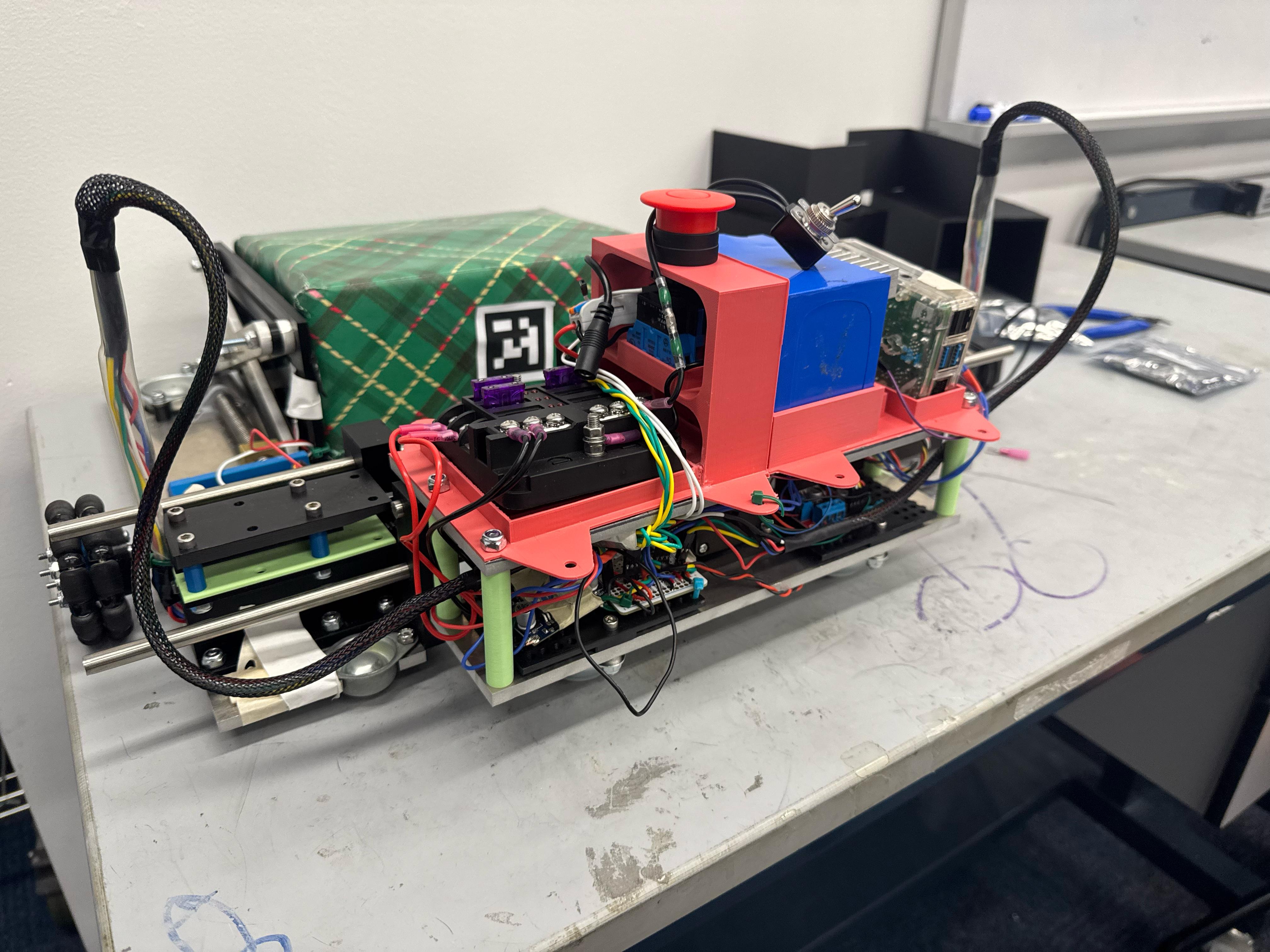
Refined electrical system
Servo Integration and State Machine
We implemented the Servo control code for the scissor lift, officially enabling Box Bot to complete the full sequence of its designed operation. Another focus for this sprint was developing and implementing a complete autonomous system. We developed a complete stat machine, guiding the robot from boot up to drop off. Each stage of this process required extensive testing, and in the end, we were unable to complete an end-to-end autonomous sequence. However, we did demonstrate functional tracking of April tags, allowing Box Bot to detect and squeeze a target box completely autonomously.
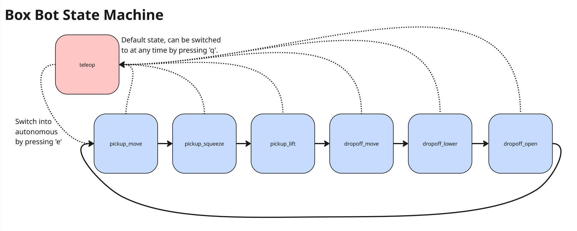
Autonomous state machine
Transitioning to the Cloud
Phase 5 focuses on moving the local Raspberry Pi logic to a centralized server, allowing a fleet of BoxBots to share depth-map data for optimized warehouse navigation.

Figure 9: Proposed fleet management architecture.
Post-Demo Day: Final Showcase & Reflection
PROJECT COMPLETION
Final competition performance, key takeaways, and future improvements.
The Final Showcase
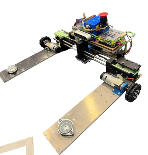
After four sprints of iteration, countless hours of effort, we were able to see our hard work drive on the demo day. During demo day, we showcased teleop driving, lifting, squeezing, and dropping. During the demo-day, we also figured out that we could stack boxes on top of eachother. We also figured out we can lift boxes of 10 pounds of 20 inches and more.
The final fully-assembled BoxBot ready for operation.
Key Learnings & Future Iterations
- Scissor Lift Upgrades: The idea of the scissor lift was great, but we didn't think through the slippage issue from the lead screw from the servo motors. This made it difficult to see what our max lift was, because the failure point was on the adapter, not the motor. However, we were able to showcase being able to lift up 10 pounds of weight. Next time, we wil make sure that will be a sturdier part.
- Autonomous: We unfortunately did not get the autonomous working. If we had more time, we will work on that, where it can detect the april tag and move to that location.
- Mechanism Speed: The servo motor was fairly slow. Next time, we will look into what might be a better application for that.
- Wiring Issues: We had trouble with the wiring, as it got often unplugged during critical testing periods. We need to come up with ways to do wiring quicker and be more consistent on it.
Throughout this project, we learned so much. We learned how to prototype, ideate, and come up with a solution for a problem that was very open ended. Although we didn't achieve the autonomous function that we wanted from the start, we were very happy with the progress that we made and how clean the design turned out to be.